
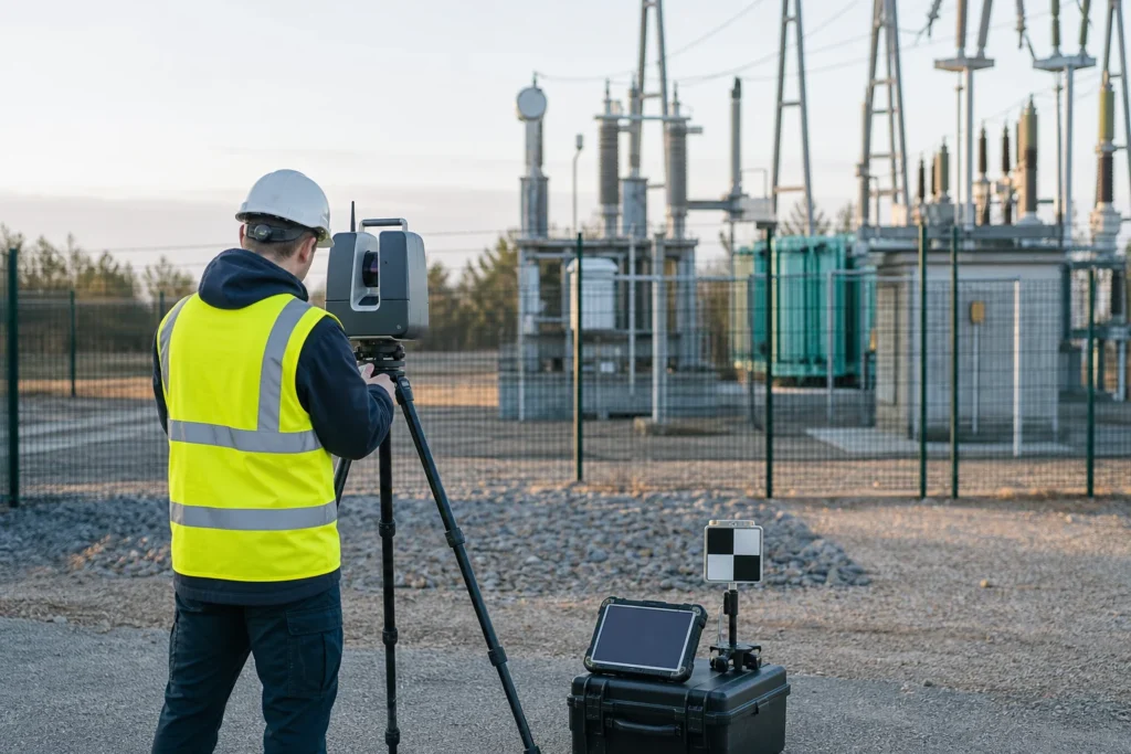
Visual note: this AI-generated editorial image illustrates the engineering context. It does not show a client, site or completed Geospatial Net project.
SLAM and RTK are sometimes compared as competing accuracy products. They solve different positioning problems. A reliable survey workflow begins with the environment, required output and acceptance test, then combines sensors and control as needed.
What RTK contributes
Real-Time Kinematic GNSS uses carrier-phase observations and corrections from a base station or network to support high-accuracy positioning. It is useful for outdoor features where satellite visibility, correction coverage, initialization and the project reference system are controlled.
RTK can be a strong choice for points and lines such as poles, chambers, valves, road features and survey control. Performance can degrade near buildings, trees, terrain, reflective surfaces, radio interference or other sources of obstruction and multipath. Store fix type, correction age, satellite geometry and repeat checks when those values matter to acceptance.
What SLAM contributes
Simultaneous Localization and Mapping estimates the sensor trajectory while building a map from observations. LiDAR-inertial SLAM can capture continuous 3D geometry through buildings, tunnels, plants, dense assets and other places where GNSS is unavailable or intermittent.
SLAM may accumulate drift when the environment lacks distinctive geometry, when movement is too fast, when loops are not closed or when dynamic objects dominate the scene. Registration quality must be tested against independent control and inspected locally.
Use a decision matrix
- Open outdoor asset points: RTK may provide the most direct controlled feature capture.
- Indoor or underground 3D geometry: SLAM or static terrestrial scanning is normally more suitable.
- Long corridors with intermittent sky view: a mobile LiDAR/SLAM trajectory can be constrained with RTK or surveyed control at intervals.
- High-detail structures: static scanning may complement SLAM where fine geometry or independent setup checks are required.
- Mixed field inventory: RTK features, SLAM point cloud, imagery and asset forms can share identifiers and control.
Control the hybrid workflow
- Define the project coordinate reference system and units.
- Set control and checkpoint requirements independently of the mobile trajectory.
- Record calibration, time synchronization and sensor configuration.
- Plan loops, overlaps and revisits for SLAM registration.
- Capture environmental conditions and known obstructions.
- Compare output to checkpoints and inspect local residuals.
- Publish known limitations with the accepted dataset.
Do not promise a universal accuracy
Accuracy depends on equipment, corrections, control, environment, geometry, procedure and processing. Product specifications should describe how the result will be tested, not rely only on a brochure value.
Engineering takeaway
SLAM and RTK solve different positioning problems. A defensible capture plan starts with environment, required outputs, control, tolerances and failure modes, then combines methods where independent checks are needed.
Decision checklist
- What accuracy, relative consistency and coverage does the use case require?
- Where will GNSS obstruction, multipath, drift or occlusion occur?
- Which independent control and repeat checks validate the capture?
- How are observations transformed into the target coordinate reference?
Sources and engineering references
- ICSM: What is GDA2020? – Official Australian datum guidance for spatial-coordinate management.
- USGS: 3DEP standards and specifications – Current technical specifications for US national elevation and LiDAR products.
- Geoscience Australia: Digital elevation data – National elevation and LiDAR products and access pathways, including ELVIS.
Official and standards links provide source context; they do not imply endorsement, legal advice or project acceptance. Confirm current rules, access conditions, licence and fitness for the specific jurisdiction and decision.